





Key Takeaways About Gas Pipe Bonding
Gas pipe bonding connects metallic gas piping to a building grounding system to carry stray voltage safely to ground. This summary is for homeowners and property managers who need to know when clamp placement, conductor sizing, and testing matter for safety and inspections.
- Identify an accessible rigid pipe section for permanent clamp placement.
- Prevent shocks by ensuring a continuous low resistance bonding path.
- Avoid attaching clamps to removable nipples or nonmetallic connectors.
- Spot warning signs like tingling appliance metal or visible sparks.
- Reduce arcing risk by using the correct conductor size and routing.
- Plan professional testing with continuity voltage and loop impedance checks.
Introduction
Gas pipe bonding is a safety step many homeowners overlook until a weak connection causes sparks or unwanted voltage on a gas line. A poor bond can create shock risks at appliances and increase the chance of arcing where metal pipes meet fittings. Knowing where clamps belong and how big the bonding conductor should be matters for both safety and code compliance. Local conditions and appliance types change the details you might see during an inspection.
Installing a bonding clamp in the wrong spot can leave sections of pipe electrically isolated and still hazardous during a fault. Electricians look for continuity across pipe runs and back to the service grounding system to confirm a reliable path. Proper conductor sizing reduces heating and deterioration in a fault and helps trip the breaker as intended. These checks prevent stray voltage from lingering on stove, furnace, or water heater connections.
Codes guide clamp placement and conductor minimums but inspectors often focus on the physical connection and test results rather than just the label on a part. Professionals use visual inspection, continuity tests, and sometimes voltage measurements to confirm a secure system. For properties in Richmond, TX and surrounding areas, code interpretations can vary slightly with the inspector and building type. Homeowners should notice warning signs like tingling appliance metal or frequent breaker trips as indicators to call an electrician.
When a gas line ties into a metallic piping system, the bonding point should allow full electrical continuity without blocking access for future service. Technicians will document clamp location, conductor size, and measured continuity value in a written report after testing. For example, a homeowner in Tomball might report a metallic stove that shocks when touched and an electrician will trace and test the bonding path. Addressing bonding issues early reduces risk of arcing and keeps appliances safe to use.
Basics Of Gas Pipe Bonding And Why It Matters
Gas pipe bonding means connecting a metallic gas piping system to the electrical grounding system so stray voltage has a path to ground. This connection reduces shock risk at appliances and lowers the chance of arcing at threaded fittings. Homeowners often ask whether bonding really prevents appliance shocks, and the clear answer is yes when the bond is continuous and sized correctly. A visible, solid clamp and an unbroken conductor usually indicate the system will carry fault current back to the service grounding electrode.
- Bonding ties pipes to the main grounding system.
- Clamps must bite clean metal, not paint or corrosion.
- Conductors should run with minimal bends and secure connections.
- Continuity testing confirms an unbroken electrical path.
Bonding clamps should be placed where pipe sections are accessible and electrically continuous, typically on a rigid section of the meter-side piping. Electricians avoid locations that might be replaced or isolated by nonmetallic connectors later. For properties in Richmond, TX, inspectors may check clamp access and test results rather than just the clamp brand. Proper placement helps ensure continuity across fittings, valves, and appliance connections during a fault situation.
Conductor sizing follows practical rules to carry fault current without overheating and to allow protective devices to trip. A correctly sized bonding conductor lowers thermal stress on the connection during a fault, which reduces arcing risk. Electricians will select a conductor based on the service characteristics and the metal piping present, and they document the choice in inspection records. For more details on conductor selection and the math behind it, see guidance about jumper sizing.
Technicians confirm a good bond with visual checks and simple tests like continuity and low-voltage measurements. They inspect the clamp for clean metal contact, proper torque, and corrosion, then use a multimeter or continuity tester across the pipe and back to the service panel. If a homeowner notices tingling from an appliance or visible sparking at a fitting, these are signs a bond needs immediate testing. A prompt electrical inspection prevents injury and reduces the chance of arcing damage to the piping system.
Where To Place Bonding Clamps On Pipes
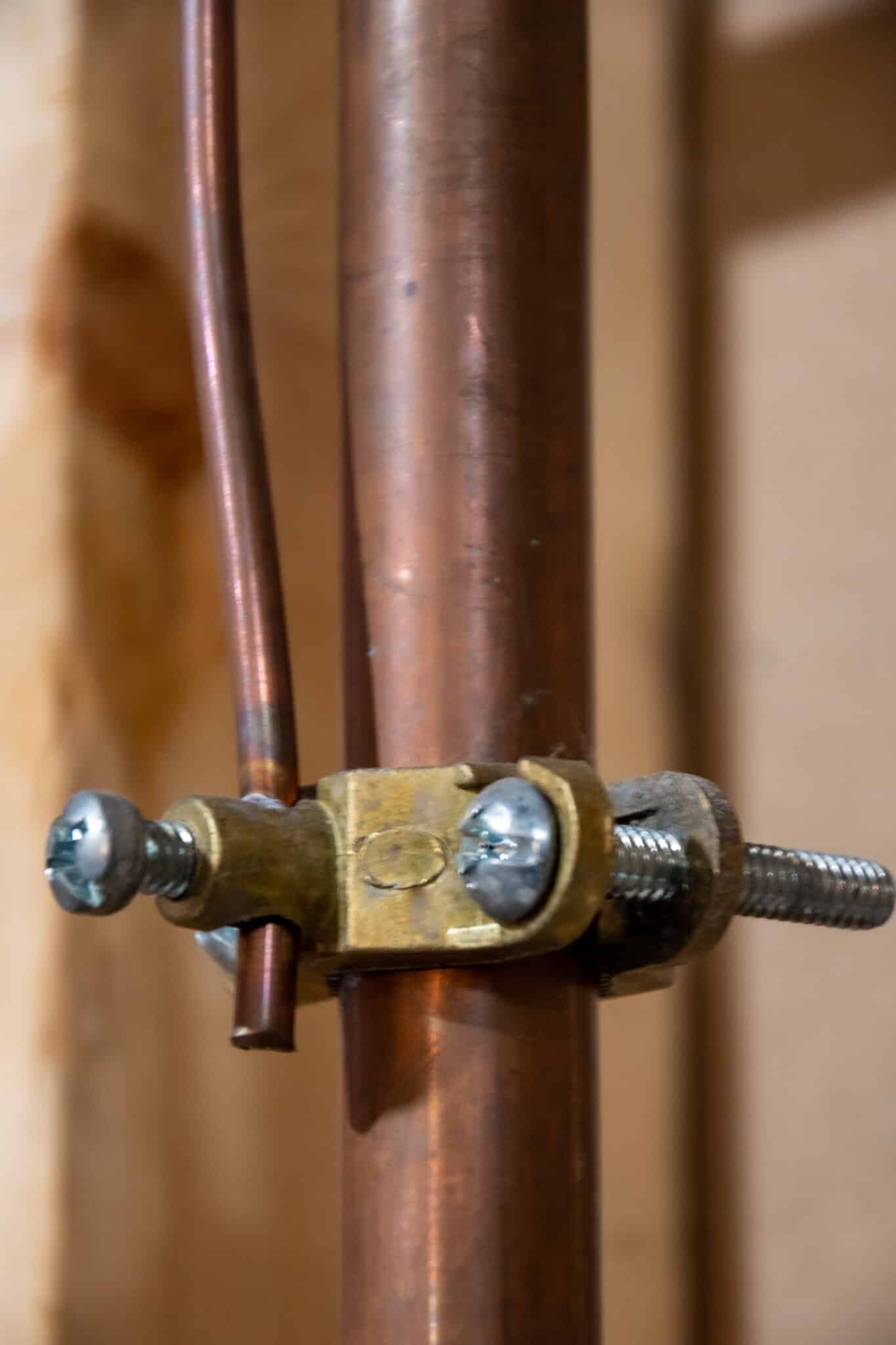
Place clamps on a clean, accessible section of rigid metal pipe where the conductor will run directly back toward the service panel. Avoid locations that are behind cabinets, buried in insulation, or likely to be removed during future work. Clamps should bite bare metal past paint, rust, or thread compound so the connection shows solid metal-to-metal contact. Electricians often rotate the clamp and wipe the spot to confirm shiny metal under the clamp before finalizing the connection.
Install clamps on the meter-side piping or on the first accessible rigid pipe downstream of the meter when possible to maximize continuity through the piping system. Do not attach the clamp to short nipple sections that can be isolated by later changes or nonmetallic connectors. When a gas appliance has a flexible connector, place the clamp on the pipe upstream of that connector to ensure the appliance stays bonded even if the flex is nonconductive. In many inspections, access and permanence of the clamp location matter as much as the clamp itself.
Position clamps so the bonding conductor follows the shortest, most direct route to the grounding system and avoids sharp bends or strain points. Secure the conductor with straps or cable ties near the clamp to prevent movement that could loosen the connection over time. Electricians sometimes mark the clamp with a corrosion-resistant tag if the pipe sits in a damp area to help future inspectors find the bond location. A clear route reduces the chance of chafing and preserves continuity under mechanical stress.
When documenting work, technicians record the clamp location, the conductor path, and continuity test results in a report for the homeowner and inspector. For homes in Tomball and for a property inspection in Richmond, TX, that record helps clarify where the bond was placed and why. If bond location interacts with ground-fault protection measures near appliances, a professional will note any impacts and refer to related grounding practices in writing. Review these details with your electrician before signing off on the job.
How To Size Bonding Conductors And Cables
Selecting the right bonding conductor size starts with the service conductor size and the type of metal piping present. Electricians often reference standard tables to match conductor ampacity to service size, ensuring the bonding conductor can carry fault current without overheating. For many residential systems, copper conductors sized from #8 AWG to #4 AWG are common, but exact choices vary with service rating and local practice. A professional will consider the smallest acceptable size that still allows protective devices to operate as intended during a fault.
Routing and securing the conductor affects its effective performance just as much as its gauge does in preventing arcing and loosening. Installers avoid sharp bends, keep the run short, and fasten the conductor at regular intervals to prevent mechanical strain at the clamp or panel. Where the conductor passes through framing, protective bushings or conduit reduce abrasion and ensure long-term integrity. Proper fastening also makes future inspections and continuity checks simpler for technicians and inspectors.
When the metallic gas piping ties into other metallic systems, the bonding conductor must maintain an uninterrupted path back to the grounding electrode system. If a neutral-ground isolation issue exists at a subpanel or appliance, a professional will diagnose it during sizing and routing decisions and may reference guidance on neutral-ground separation. Testing the path after installation confirms the conductor size and routing actually provide low impedance and a reliable fault path for the protection devices.
Technicians verify conductor adequacy with measured resistance and continuity tests rather than visual estimates alone, using a clamp meter or low-resistance ohmmeter for clarity. They document readings in the service report and compare them to expected values to confirm a secure connection to the grounding system. For a homeowner in Tomball or during inspections in Richmond, TX, these recorded results help demonstrate compliance and provide data for any follow-up maintenance. If measurements show high resistance, the electrician will upsized conductor or rework connections until readings meet safety expectations.
Applicable Electrical And Gas Code References
Most electrical and gas codes reference bonding of metallic gas piping to the grounding system and require a permanent low-impedance connection. Professionals commonly consult an accepted electrical code and a plumbing or gas code to confirm where bonding clamps and conductors belong. Inspectors focus on measurable outcomes like low resistance and visible secure connections rather than a specific brand of clamp or conductor. For homeowners, knowing which codes guide inspectors helps when scheduling an electrician or preparing for an inspection in Tomball.
- Codes require bonding to the grounding electrode system.
- Clamp access and permanence are commonly inspected.
- Conductor sizing ties to service capacity and fault current.
- Testing records often determine final compliance findings.
Electricians typically reference a national electrical model code and a recognized plumbing or gas code for guidance on bonding practices. These references provide tables and principles for conductor sizing and acceptable bonding methods rather than a single mandated product. During inspection, professionals compare test results to the practical expectations in those codes to decide if rework is needed. For properties undergoing appliance replacement or panel upgrades in Richmond, TX, code guidance clarifies acceptable bond changes.
Grounding electrode and bonding records form part of a complete inspection file and may require follow-up testing like ground rod resistance checks for full documentation. Technicians often include readings, clamp location notes, and conductor size on the written report for inspectors and homeowners. A useful related check is keeping grounding electrode test results alongside bonding verification, homeowners can read more about grounding tests such as ground rod testing to understand that link. When codes leave interpretation to the inspector, documented measurements help resolve questions about safety and compliance.
How Electricians Verify Continuity And Integrity
Electricians start by isolating the bonding conductor path and visually inspecting each connection for clean metal contact and secure hardware. They then use a continuity tester or low-resistance ohmmeter to measure resistance between the gas pipe and the service grounding point. Readings that show very low ohms confirm a continuous path and indicate the conductor and clamp make good electrical contact. If resistance is higher than expected, the technician re-cleans the contact area and retests until acceptable values appear.
Technicians also perform a voltage test to detect stray voltage on the piping that continuity alone might not show under no-load conditions. A measured voltage between the pipe and a known grounded point can reveal neutral-to-ground faults or parallel paths that need correction. When electricians find voltage, they trace the source using systematic checks at appliances, junction boxes, and the main service panel. Documented voltage readings help prioritize repairs and clarify whether bonding or wiring faults exist.
For large or complex systems, crews use a clamp-on ground resistance meter around the bonding conductor to estimate loop impedance without disconnecting conductors. They compare loop impedance to expected values so protective devices will trip properly during a fault and prevent prolonged heating. When measurements show high loop impedance, common fixes include shortening the conductor, using a larger gauge, or improving clamp contact to reduce thermal and arcing risk. Each repair is followed by repeat testing and written recording of final readings for inspection purposes.
Diagnostic steps include checking appliance flexible connectors, threaded fittings, and isolation devices that may interrupt continuity in the piping run. For example, an electrician will inspect the area where a flexible appliance connector meets the gas pipe and confirm the clamp is upstream of any nonmetallic section. Homeowners in Tomball and inspectors in Richmond, TX often request the written test results after this verification to document safety. If tests reveal persistent issues, the professional will advise further electrical system troubleshooting or corrective bonding work.
Common Causes Of Bonding Failures And Why It Happens
Mechanical looseness at clamps and connectors is a common cause of bond failure because vibration or thermal cycling breaks metal-to-metal contact. Corrosion under a clamp often raises resistance and may hide beneath paint or thread sealant, so technicians clean the contact area before retesting. Improperly routed conductors that rub against framing or pass through sharp edges will fray insulation and create high-resistance spots that fail under fault current. Electricians look for these physical signs during an inspection and document any required repairs in a written report.
Incorrect clamp placement causes isolation when the clamp is on a removable nipple or on a nonconductive section, creating a false sense of safety. Flexible appliance connectors can be nonconductive internally, so a clamp positioned downstream leaves the appliance electrically floating during a fault. Field measurements that show unexpected voltage or resistance prompt a tracer investigation to find the exact interruption. For homes in Tomball, these misplaced clamps are often found during appliance replacement checks.
Undersized or damaged bonding conductors increase loop impedance and delay protective device operation, which raises heating and arcing risks at pipe joints. Poor terminations at the service panel or grounding electrode can mimic pipe bonding failures, making systematic checks essential to find the real weak link. Professionals use low-resistance ohmmeters and loop impedance tests to distinguish conductor size problems from bad clamps or corroded metal. When tests point to conductor issues, technicians recommend upsizing or replacing the conductor and then retesting to confirm improvement.
Hidden interruptions such as dielectric unions, isolation valves, or buried plastic sections break continuity and often go unnoticed until testing reveals a problem. Tracing continuity across the entire piping network helps locate these hidden breaks so corrective bonding can be placed in an accessible, permanent spot. Electricians may also inspect nearby electrical panels and bonding electrodes to rule out alternate fault paths that reduce the effectiveness of the pipe bond. Written test results and photos help homeowners and inspectors confirm that repairs restored a low-impedance path.
Human error during installation and later maintenance is another frequent cause of failure when clamps are loosely torqued or conductors are pinched during remodeling work. Routine checks during remodels or appliance swaps prevent these oversights, and a short continuity test quickly flags newly introduced faults. For complex grounding questions, professionals often refer to general grounding guidance such as information found on the electrical grounding resource. Inspectors in Richmond, TX sometimes require these records before final approval to verify permanent corrective actions.
Warning Signs Of Poor Bonding And When To Act
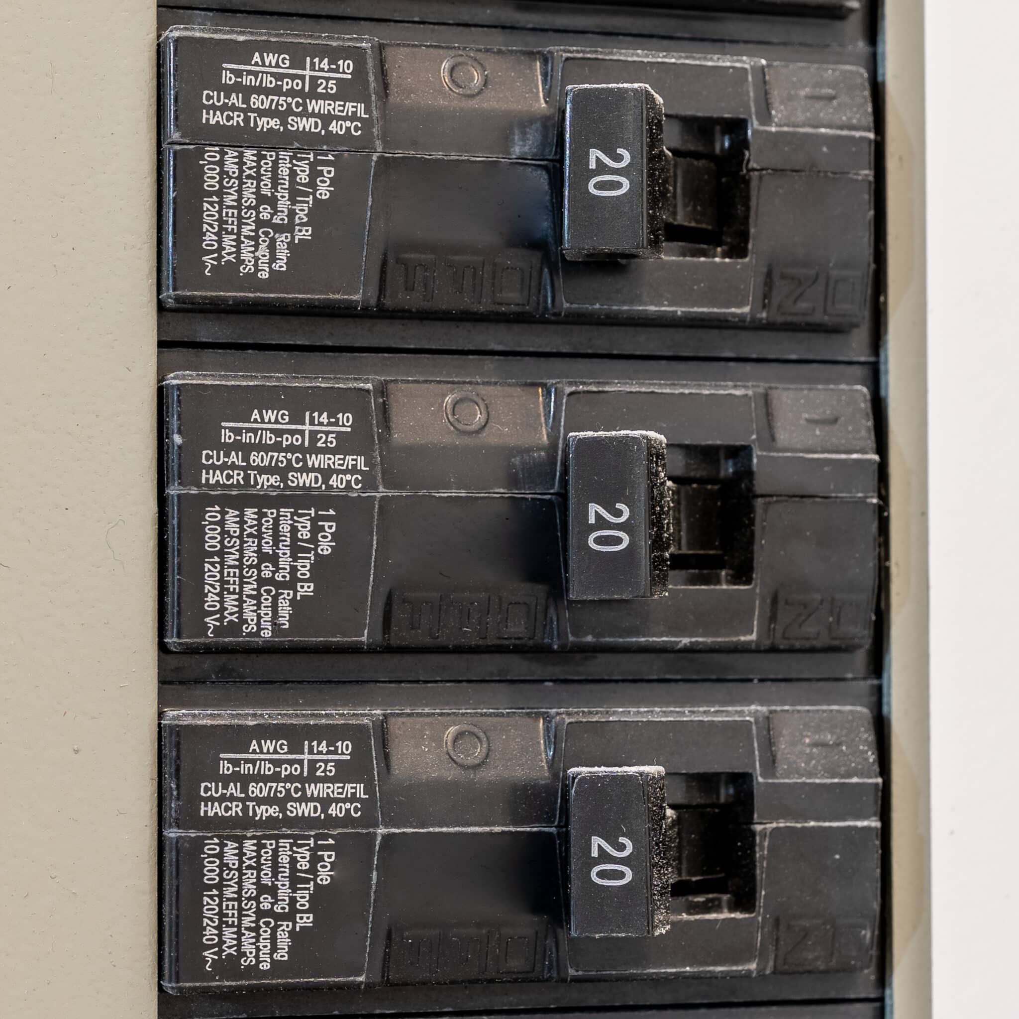
If you notice a metallic appliance delivering a shock when touched, this can indicate poor gas pipe bonding and needs prompt attention. Another warning sign is intermittent arcing or visible sparks at threaded pipe fittings during appliance startup or heavy equipment operation. Frequent tripping of nearby breakers or GFCIs can point to a stray fault finding a path through piping instead of the grounding electrode. Any unexplained buzzing sounds near the service panel or piping junction should trigger an inspection by a qualified electrician.
- Metallic appliance gives a mild shock.
- Sparks appear at pipe joints or fittings.
- Frequent breaker or GFCI trips occur.
- Unusual buzzing near panels or piping exists.
- Visible corrosion or loose clamp hardware is present.
During diagnosis, a professional will first look for loose clamps and corroded contact points on accessible piping sections. They will perform a continuity test between the gas pipe and the main service grounding conductor to measure resistance. A voltage measurement between the pipe and a known earth reference helps locate stray neutral faults or parallel paths that continuity tests alone might miss. Technicians then trace back through appliance flex connectors, valves, and isolation devices to find the interruption source.
If a homeowner in Tomball detects tingling on stove casings, they should stop using the appliance and call an electrician to prevent injury. For properties in Richmond, TX, inspectors may require written test results after repairs to verify low-resistance bonding and restored safety. Professionals will make corrective changes such as repositioning clamps to permanent rigid pipe, cleaning surfaces, or upsizing conductors when measurements exceed acceptable values. Always hire a licensed electrician to perform these tests and repairs because they carry the proper tools and safety procedures.
When Homeowners Should Call A Professional Service
If you notice warning signs or if bonding work requires accessing the service panel, call a licensed electrician to avoid unsafe DIY work. A professional will use proper tools and safe procedures to disconnect, test, and reattach conductors with the main service isolated. Trying to work near the service without training risks shock, code violations, and improper repairs that leave hazards. Contacting a pro keeps the job documented for inspections and future buyers.
When appliances repeatedly trip protective devices or show intermittent arcing, schedule an inspection promptly so the electrician can perform loop impedance and voltage tracing. The technician will locate hidden interruptions such as dielectric unions or buried nonmetallic sections that homeowners cannot see. These diagnostics often require meter readings at multiple points and temporary disconnects to isolate the fault. A timely service call reduces the chance of fire or progressive pipe damage from arcing.
If clamp locations need relocation to permanent rigid pipe or conductor upsizing is likely, hire a professional who understands conductor sizing and grounding requirements. The electrician will calculate an appropriate conductor size and route while minimizing bends and mechanical strain on the run. They will also clean and torque connections to specifications and then retest continuity to confirm low resistance. Proper documentation of these steps supports inspector acceptance in Richmond, TX and other local reviews.
For homeowners experiencing mild shocks from appliance casings, stop using the appliance and call for an urgent evaluation rather than attempting temporary fixes. A qualified technician will perform continuity, resistance, and voltage checks to determine if the bonding path or another wiring fault causes the symptom. They can provide a written report and recommend corrective work such as clamp repositioning or conductor replacement. Read more about preventing shocks and safe next steps in this helpful resource for homeowners.
Frequently Asked Questions
Where should a bonding clamp be placed on gas piping?
Place the bonding clamp on the metal gas piping at the first accessible point downstream of the meter or regulator, avoiding painted or heavily corroded surfaces. Clamp to a straight pipe section that allows a clean metal-to-metal contact and steady conductor routing. Electricians avoid fittings, unions, or flexible connectors as attachment points to reduce resistance and arcing risk. If you are unsure or the piping condition looks unsafe, stop and hire a licensed electrician to perform Gas pipe bonding and verification.
How do electricians size a gas pipe bonding conductor?
Electricians size a gas pipe bonding conductor by matching the conductor to the largest equipment grounding conductor in the same circuit. They consult the electrical service grounding size tables and consider the meter, service conductors, and bonding jumper route. If metallic gas piping ties into the building grounding system, they typically use copper conductors sized to meet code minimums and reduce voltage between bonded parts. Exercise caution around gas lines and live equipment and hire a licensed electrician to confirm proper sizing and connections.
What tests confirm a safe bond and continuity?
Electricians confirm continuity with a digital multimeter measuring near-zero ohms between the bonding clamp and the service grounding electrode. They also perform a clamp-on ground resistance test to verify low loop impedance without disconnecting the pipe. Visual inspection checks for clean metal contact, secure clamp placement, and undamaged conductor insulation. If readings fall outside acceptable ranges or you suspect a hazard, stop and call a licensed electrician for correction and retest.
Can gas pipe bonding stop appliance shocks?
Proper gas pipe bonding can reduce stray voltage and lower the chance of appliance shocks by creating a low-impedance path to the grounding system. It does not fix internal appliance faults or correct poor appliance grounding, so shocks can still occur. Electricians test continuity and bonding effectiveness with a clamp meter or continuity tester to confirm a solid connection. If you suspect shocks or persistent stray voltage, stop using the appliance and hire a licensed electrician to inspect and repair safely.
What signs mean the pipe bond or clamp has failed?
Visible corrosion, loose or missing clamp hardware, burn marks, or melted insulation on the bonding conductor indicate a failed pipe bond. You may notice intermittent appliance shocks, buzzing from outlets, or tripped breakers that suggest poor continuity. An electrician will confirm failure with a continuity test and recorded low or open readings between the pipe and grounding electrode. If you see these signs, stop using affected appliances and call a licensed electrician because a failed bond raises shock and arcing hazards.